


To further protect your vehicle from theft, it has been fitted with an engine immobilising system (Fiat CODE system) which is automatically activated when the ignition key is removed.
An electronic device, in fact, is fitted in each ignition key grip. The device transmits a radio-frequency signal when the engine is started through a special aerial built into the ignition switch. The modulate signal, which changes each time the engine is started, is the password by means of which the control unit recognises the key and enables to start the engine.
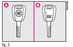
KEYS fig. 2
The following keys are provided with the vehicle:
– two keys A when the vehicle is not equipped with remote control;
– key A and key B when the vehicle is equipped with door lock remote control.
– Key A is the key that is used normally.
It will:
– start the engine;
– lock/unlock front doors;
– lock/unlock the rear doors or the tailgate;
– lock/unlock the side doors, Cargo versions only;
– deactivate the passenger’s airbag.
The key B, with a built-in remote control, has the same functions as key A in vehicles with door lock remote control.
The CODE card fig. 3 is also supplied with the keys and bears the following:
a - the electronic code to be used for emergency starting (see “Emergency start-up” in section “In an emergency”);
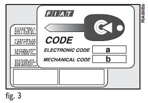
b - the mechanical key code to be given to the Fiat Dealership when ordering duplicate keys.
Keep the CODE card in a safe place.
Make sure you have the electronic code of the CODE card with you at all times in the event you have to perform an emergency start-up.
See also:
How To Use This Manual
Consult the Table of Contents to determine which section contains the information
you desire.
Since the specification of your vehicle depends on the items of equipment ordered,
certain descriptio ...
Spare Tire Removal
The spare tire is stowed to the underbody below the cargo area.
1. Remove the plug located in the rear cargo area.
Winch Access Plug
2. Fit the wrench tool over the drive nut. Use the wrench to ...
ABS
The vehicle can be fitted with an ABS braking system, which prevents the wheels
from locking when braking, makes the most of road grip and gives the best control
when emergency braking under diffi ...