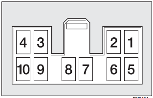
The system set-up, combined with radio consists of:
❒ dual-purpose aerial (sound system + cellular phone 900/1800 MHz), on the car
roof;
❒ dual-purpose connection wires and ten-pin connector wiring.
The connector is located between the steering column and the central console.
Cellular phone set-up combined with sound system set-up, consists of:
❒ dual-purpose aerial (sound system + cellular phone 900/1800 MHz), on the car
roof;
❒ dual-purpose speaker (sound system + cellular phone), on passenger’s door;
❒ dual-purpose connection wires and ten-pin connector wiring.
The connector is located between the steering column and the central console.
The hands-free telephone you purchase will need to be compatible with your cellular telephone.
WARNING
The maximum power applicable to the aerial is 20W.

The wiring diagram is the following:
1 Sound system MUTE function
2 Spare
3 Cellular phone INPUT earth signal (*)
4 Cellular phone INPUT signal (*)
5 Dual-purpose speaker on passenger’s door (+) (**)
6 Dual-purpose speaker on passenger’s door (–) (**)
7 Ignition switch power (+15)
8 Spare
9 Battery power (+)
10 Earth
(*) Sound system.
(**) Sound-system set-up.
We recommend installing the microphone near the front ceiling light.
Have the cellular telephone and the connections to the system installed by a Fiat Dealership only. This will ensure the best results and prevent problems which could affect the car safety.
See also:
Traction
When driving on wet or slushy roads, it is possible for a wedge of water to build
up between the tire and road surface. This is known as hydroplaning and may cause
partial or complete loss of vehi ...
Left-hand direction indicator
The warning light on the dial turns on when the direction indicator control lever
is moved downwards or, together with the right indicator, when the hazard warning
light button is pressed. ...
Set clock
Press button h. Each pulse on the button will obtain increase by one unit. Automatic
fast increase is obtained by keeping the button pressed for few seconds. When you
are near the required value, ...


