![]() WARNING!
WARNING!
Carefully follow these tire changing warnings to help prevent personal injury
or damage to your vehicle:
• Always park on a firm, level surface as far from the edge of the roadway as
possible before raising the vehicle.
• Turn on the Hazard Warning flashers.
• Block the wheel diagonally opposite the wheel to be raised.
• Set the parking brake firmly and set an automatic transmission in PARK; a manual
transmission in REVERSE.
• Never start or run the engine with the vehicle on a jack.
• Do not let anyone sit in the vehicle when it is on a jack.
• Do not get under the vehicle when it is on a jack.
• Only use the jack in the positions indicated and for lifting this vehicle during
a tire change.
• If working on or near a roadway, be extremely careful of motor traffic.
• To assure that spare tires, flat or inflated, are securely stowed, spares must
be stowed with the valve stem facing the ground.

Jack Warning Label
![]() NOTE: Refer to the “Compact Spare Tire” section of the “Tires-General Information”
under “Starting And Operating” for information about the spare tire, it s use, and
operation.
NOTE: Refer to the “Compact Spare Tire” section of the “Tires-General Information”
under “Starting And Operating” for information about the spare tire, it s use, and
operation.
![]() CAUTION!
CAUTION!
Do not attempt to raise the vehicle by jacking on locations other than those indicated in the Jacking Instructions for this vehicle.
1. Remove the scissors jack and tool bag from under the driver’s seat.
2. Loosen, but do not remove, the wheel bolts by turning them to the left one turn while the wheel is still on the ground.
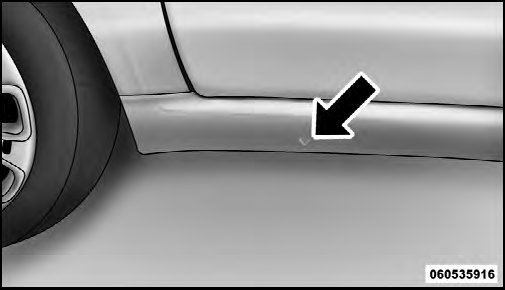
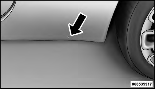
![]() NOTE: There are front and rear jacking locations on each side of the body (as
indicated by the triangular lift point symbol on the sill molding).
NOTE: There are front and rear jacking locations on each side of the body (as
indicated by the triangular lift point symbol on the sill molding).

Front Jacking
Location

Rear Jacking Location
Do not raise the vehicle until you are sure the jack is securely engaged.
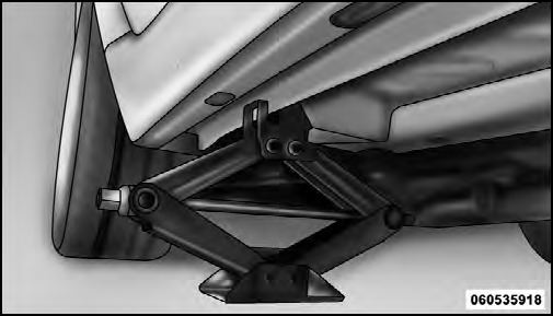
3. Turn the jack screw to the left until the jack can be placed under the jacking location. Once the jack is positioned, turn the jack screw to the right until the jack head is properly engaged with the lift area closest to the wheel to be changed.

Jacking Location
![]() WARNING!
WARNING!
Raising the vehicle higher than necessary can make the vehicle less stable. It could slip off the jack and hurt someone near it. Raise the vehicle only enough to remove the tire.
4. Using the swivel wrench, raise the vehicle by turning the jack screw to the right. Raise the vehicle only until the tire just clears the surface and enough clearance is obtained to install the spare tire. Minimum tire lift provides maximum stability.
5. Remove the wheel bolts and pull the wheel off the hub. For vehicles equipped with aluminum wheels, the center caps must be removed to remove the wheel bolts.
![]() WARNING!
WARNING!
To avoid the risk of forcing the vehicle off the jack, do not fully tighten the wheel bolts until the vehicle has been lowered. Failure to follow this warning may result in personal injury.
![]() CAUTION!
CAUTION!
Be sure to mount the spare tire with the valve stem facing outward. The vehicle could be damaged if the spare tire is mounted incorrectly.
![]() WARNING!
WARNING!
To avoid possible personal injury, handle the wheel covers with care to avoid contact with any sharp edges.
![]() NOTE: The wheel cover is held on the wheel by the wheel bolts. When reinstalling
the original wheel, properly align the wheel cover to the valve stem, place the
wheel cover onto the wheel, then install the wheel bolts.
NOTE: The wheel cover is held on the wheel by the wheel bolts. When reinstalling
the original wheel, properly align the wheel cover to the valve stem, place the
wheel cover onto the wheel, then install the wheel bolts.
6. Install the spare wheel and wheel bolts with the cone shaped end of the bolts toward the wheel. Lightly tighten the bolts. To avoid the risk of forcing the vehicle off the jack, do not tighten the bolts fully until the vehicle has been lowered.
7. Lower the vehicle by turning the jack screw to the left.
8. Finish tightening the bolts. Push down on the wrench while tightening the wheel bolts. Alternate bolts until each bolt has been tightened twice. The correct wheel bolt torque is 63 ft lbs (85 N·m) for steel wheels and 75 ft lbs (100 N·m) for aluminum wheels. If you doubt that you have tightened the bolts correctly, have them checked with a torque wrench by your authorized dealer or service station.
9. Disassemble the jack and tools and place them in the bag. Stow it under the driver’s seat and secure the bag to the floor with the straps attached to the floor of the vehicle.
![]() WARNING!
WARNING!
A loose tire or jack thrown forward in a collision or hard stop could endanger the occupants of the vehicle.
Always stow the jack parts and the spare tire in the places provided.
10. Place the deflated (flat) tire in the cargo area. Have the tire repaired or replaced as soon as possible.
![]() WARNING!
WARNING!
A loose tire thrown forward in a collision or hard stop could injure the occupants in the vehicle. Have the deflated (flat) tire repaired or replaced immediately.
11. Check the spare tire pressure as soon as possible.
Correct the tire pressure as required.
See also:
Refuelling
To guarantee full tank filling, carry out two refueling operations after the
first click of the fuel delivery gun.
Avoid further topping up operations that could cause damages to the fuel system.
...
Starting procedure for petrol versions
1) Ensure that the handbrake is up.
2) Put the gear lever into neutral.
3) Press the clutch pedal fully down, without pressing the accelerator.
4) Turn the ignition key to AVV and let it go the mom ...
Seat belts not fastened
(red)
The warning light on the dial turns on glowing steadily with vehicle stationary
and driver’s or passenger’s seat belt not fastened correctly.
The warning light will turn on flashing when, ...


